Ball milling and rod grinding are caused by the rotation of the cylinder to cause the grinding medium inside to move, thus causing the grinding effect on the ore. There are many similarities in the movement of the grinding medium contained in them. The motion state of the steel ball has been studied sufficiently, so it is chosen as a representative of inflammation. Since the grinding effect is the effect of the steel ball movement, the purpose of studying the kinematics of the steel ball is to fundamentally discuss the productivity of the mill, the power consumed, and the best main grinding conditions.
Photographs of steel ball motions in the mill can be summarized into three typical states in the following figures: sloping, throwing, and centrifugal.

Fig.1 The movement state of the steel ball installed inside the mill (a) sloping type; (b) throwing type; (c) centrifugal operation
If the rotational speed of the mill is not high, all of the ball loads are deflected upward by a certain angle, wherein each of the steel balls rotates about its own axis. When the angle of inclination of the ball exceeds the natural angle of repose of the ball on the surface of the ball, the ball rolls down the slope. This state of motion of the steel ball is called sloping, as shown in (a) of Figure 1. In the pulverized working mill, the mineral material is subjected to abrasion and peeling between the steel balls. If the rotation speed of the mill is high enough, the steel ball rotates and rises to a certain height with the circular motion of the inner wall of the cylinder, and then the parabola falls. The place where the steel ball falls is called the foot area, and the steel ball is tumbling strongly. This state of motion, as shown in (b) of Figure 1, is called throwing. In the grinding machine of the throwing work, the mineral material is subjected to the abrasion and peeling action of the steel ball in the circular curved motion zone, and the impact of the falling steel ball and the sharply rolling steel ball in the foot area. If the speed of the mill is high above a certain critical value, the steel ball will stick to the liner and no longer fall. This state is called centrifugation, as shown in (c) of Figure 1. When the centrifugal operation occurs, the mineral material is also attached to the lining. All of the above cases refer to the fact that a certain number of steel balls are contained in the mill. If there are only a small number of balls in the mill, they only oscillate at the lowest point in the mill, and the three situations mentioned above do not occur. Using the motion state of the medium in the grinding machine to study its movement law, this century has begun in the 1920s, and Howard, Davis, Levinson, and Wang Rendong of China have all done this. work.
There is still a lack of research on the mechanics of steel ball leeching movement, and only the throwing type will be mentioned later.
Take a closer look at the following photos of throwing and centrifuging.

figure 2
The actual speed is 75% of the critical value, and the ball ball movement condition is different when the ball load (the percentage of the ratio of the volume of the steel ball to the internal volume of the mill - the ball loading rate, expressed by φ)

image 3
The actual speed is equal to the critical value, the movement of the steel ball under different ball loads [next]
These photos give us a deep impression: the steel ball in the mill, the throwing motion or the centrifugal operation and the height of the drop of the ball are determined by the speed of the mill and the amount of ball loaded. When the rotational speed is 75% of the critical value, the more the ball is loaded, the greater the throwing height of the steel ball. When the speed is equal to the critical value, the ball loading rate will be above 40%. These impressions make us take the weight of the ball and the centrifugal force of the steel movement as the starting point when analyzing the movement of the steel ball.
The photograph of the former grinder as a drop-off worker is simplified to Fig. 4(a), the foot area is omitted, and the falling point of the ball as a parabola is assumed to be the starting point of the circular curve motion.
When the steel ball moves within the mill, it produces a relative motion that slides down the liner. But photos taken by Davis show that if there is only steel balls and water in the mill, the sliding phenomenon is obvious, and the steel ball cannot rise to the theoretical height it should reach. If sand is added, the sliding phenomenon is eliminated. Some tests have pointed out that when there is only steel ball in the mill without water and ore, the ball load has a sliding phenomenon of 10%, 20% and 30%. When the ball load is above 40%, the sliding stops. The mechanical analysis of the ball load with sliding, RT Huji has been studied, and Rose and RME Sullivan have also been discussed. The grinding medium kinematics mentioned later basically belongs to Davis's category that does not involve the sliding of steel balls. This theory does not consider the frictional characteristics of the ball load, neglects the mutual influence of the balls in the same sphere, and neglects the mutual interference between the spheres, and the majority of the mills in production are roughly related to the theory of Davis. Compliance, so it is still the basis for mill calculations and conducting new research.
As shown in the figure below, a steel ball A 1 is randomly taken in the ball load, which is under the weight G of the ball and has a centrifugal force C. The tangential component force T of T (T=Gsina) causes the particle point A 1 to move in the tangential direction; the normal component force N of N (N=Gcosa) is the same in the directions of the third and fourth quadrants as the centrifugal force C, in the second The quadrant is opposite to the direction of C. The reaction force of the resultant force of C and N, combined with the friction coefficient (f) at the contact with A 1 , constitutes the friction force F, which is opposite to the T force and prevents the T force from moving in the tangential direction. When there is no relative movement between the steel ball and the cylinder wall, the T and F forces are equal. The steel ball is pressed by the force C and the force N, and is integrated with the mill, and rises to the A 3 point with the same linear speed of the mill. Here, the forces C and the force N are equal in opposite directions, F=0, and the tangential component force T is offset by the thrust of the following ball ascending. As a result, the steel ball is detached from the wall of the cylinder and becomes free, like an angle with the horizontal line and throwing the object at a speed, and is parabolically dropped by its own weight.

Figure 4 Force acting on the steel ball
When the mill speed is too high, the ball rises to the apex Z, but the centrifugal force C is larger than the weight G of the steel ball, the steel ball does not fall, and the centrifugal operation occurs.
When the rotation speed is lower, less than A 3 point, N force and C force are equal, the steel ball is parabolic, the N force is related to the weight of the ball and the position of the ball, and the C force is related to the weight of the ball and the rotation speed of the mill. Therefore, the height to which the steel ball can rise is determined by the ball load and the mill speed, which will be described in detail later.
Each of the balls in the ball is subjected to the force of the T and F forces of equal magnitude and opposite directions, and thus rotates around its own axis, as shown in Fig. 4(b).
Describe:
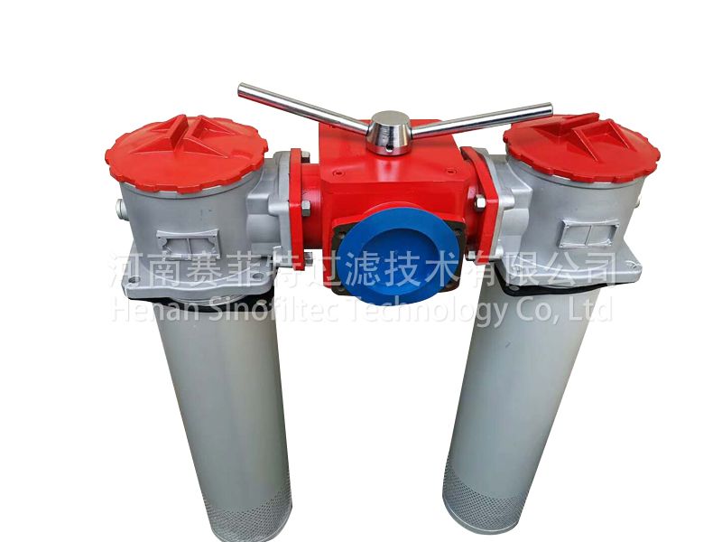
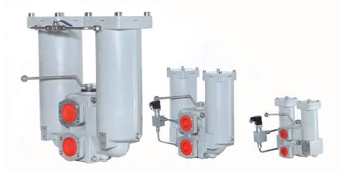
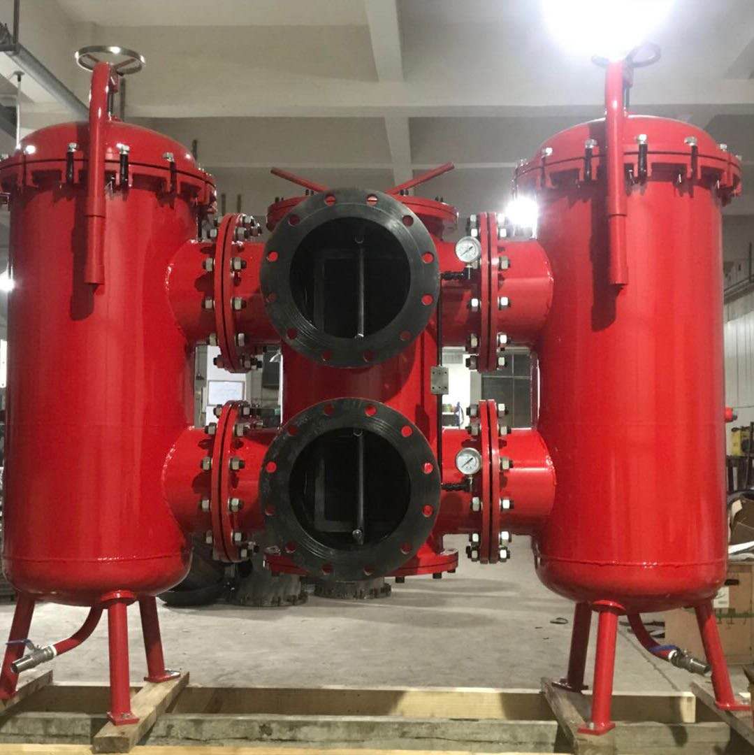
Duplex filters, also called double-barrel return pipeline filters, are composed of two single-barrel filters and two six-way reversing valves, which have simple structure, easy to use, and with by-pass valve and filter core pollution clogging transmitter, in order to ensure the safety of the system.
Characteristics:
The double-barrel filter is mainly installed on the return pipeline of the hydraulic system. Various kinds of dirt such as abrasive particles produced by various hydraulic components in the working process can be intercepted by setting the Oil Filter of the return pipeline to avoid returning to the fuel tank again. Inhaled again by a hydraulic pump. The allowable pressure difference of the oil filter in the return pipeline is 0.3 ~ 0.5mpa. according to the different pressure level. The accuracy is determined according to the oil contamination requirement. In the working process, when the filter core is clogged to a certain extent and the filter core needs to be cleaned or replaced, it is necessary to stop the mainframe operation to replace the filter element, which is not only a waste of time but also can not meet the needs of continuous operation of the main engine. The double-barrel filter can effectively solve the defect of single-barrel filter and can clean or replace the filter core without stopping to ensure the mainframe work normally and continuously. When one filter core is blocked and needs to be replaced, it is not necessary to stop the mainframe operation. Just open the pressure balance valve and turn on the reversing valve. The other filter can take part in the operation and then replace the blocked filter element
Applications:
1. Metallurgy: used for filtration of rolling mill, continuous casting machine hydraulic system and various lubricating equipment.
2. Petrochemical: separation and recovery of products and intermediate products in refining and chemical production, filtration of oil well water and natural gas.
3. Textile: purification and uniform filtration of polyester melt during drawing, protection and filtration of air compressor, deoiling and dewatering of compressed gas.
4. electronics and pharmacy: reverse osmosis water, deionized water pre-treatment filtration, washing liquid and glucose pretreatment filtration.
5. Thermal power and nuclear power: gas turbine, boiler lubrication system, speed control system, bypass control system oil purification, feed water pump, fan and dust removal system purification.
6. Processing equipment: paper machinery, mining machinery, injection molding machine and large precision machinery lubrication system and compressed air purification, tobacco processing equipment and spraying equipment filtering.
Product types:
SZU-A series Duplex oil return Line Filters
· SQU-A series Duplex oil return line filters
· SWU-A series Duplex oil return line filters
· SXU-A series Duplex oil return line filters
· SRLF series Duplex oil return line filters
· SRFB series Duplex tank mounted oil return filters
· SRFA Duplex tank mounted mini-type oil return filters
· SMF series Middle pressure line filters
· SLLF series Duplex lubricant filters
· SGF series Duplex high pressure line filters
· SDRLF series Duplex high flow rate oil return line filters


Duplex Filters
Duplex Filter,Duplex Cartridge Filter,Duplex Type Edible Oil Filter,Duplex Lube Oil Filter
Henan Sinofiltec Technology Co.,Ltd , https://www.airfilters.pl