Research and Application of Centralized Monitoring Scheme for Auxiliary System (Workshop) of Thermal Power Plant
Abstract: This paper analyzes the centralized monitoring of the auxiliary system (workshop), and proposes the solution and application prospect of the centralized monitoring of the auxiliary system (workshop).
Introduction The auxiliary systems (workshops) are located far apart from each other in terms of physical locations, the traditional control methods are relatively independent, and the forms of network connections are diverse, thus inconveniencing monitoring and management. In recent years, due to the continuous development of control technology and the continuous renewal of management concepts, thermal power plants have put forward higher requirements for the monitoring system of auxiliary systems: not only to reduce investment, but also to improve the control level of auxiliary systems (workshops). Therefore, the control of the auxiliary system should improve the management and integration level of the auxiliary system (workshop) of the power plant by strengthening management and reducing the number of shifts.
I. Status of auxiliary system (workshop) control
In 2000, the coal-fired demonstration power plant and the newly promulgated "Technical Regulations for Design of Thermal Power Plants" put forward new requirements for the control methods of auxiliary systems (workshops), that is, "adjacent auxiliary production workshops or similar auxiliary process systems should be merged. The control system and control points, auxiliary workshop control points should not exceed three (coal, ash, and water), and the remaining workshops are designed according to unattended operation. The control technology of PLC+ PC is widely used in auxiliary systems (workshops) because of the enhanced safety and reliability of independent system operation. The status of the auxiliary control system can be summarized as follows:
(1) Most of the auxiliary control systems use more than 3 sets of PLC+ PCs, with more duty points.
(2) Some process equipment comes with a small PLC to control and form an independent control system.
(3) The auxiliary control system is often supplied by different manufacturers, resulting in different design styles and the types of PLCs, CPUs, and card types of each control system are not uniform.
(4) The main auxiliary systems such as coal transportation system, fuel pump room, ash removal system, chemical water treatment system, and circulating water system need to provide a special control room and a certain number of operating personnel to perform on-duty operation.
(5) Each control system is independent of each other, and there is almost no information exchange between system information and each main control room.
Therefore, the status quo of auxiliary systems (workshops) brings the following problems to operation and maintenance:
(1) The decentralized control room not only increases investment and operation and maintenance costs (such as decoration, air conditioning, etc.), but also is not easy to manage.
(2) There are more staff on duty. General crew masters are equipped with 5 crews per crew, and staff on duty for external equipment can be equipped with around 15 staff.
(3) There is very little information exchange between each auxiliary system (workshop) and the main control room. The control requirements of the main control room for the auxiliary system (workshop) are often contacted by telephone. This method is extremely inconvenient and lacks timeliness.
(4) Each auxiliary control system uses different hardware and software, which poses certain difficulties for spare parts management, personnel training and maintenance.
Second, the auxiliary system (workshop) centralized monitoring program research
2.1 Design of centralized monitoring points for auxiliary systems (workshops) Article 4.1.8 of the DL/T5227-2005 Technical Regulations for Thermal Power Plant Auxiliary Systems (Workshops) Thermal Engineering Designation clearly states that “auxiliary (system) workshops should adopt PLC control, Small DCS or dedicated controllers can also be used for technical and economic verification." Therefore, starting from a technical point of view, centralized monitoring of auxiliary systems (workshops) can be implemented using both PLC and DCS. According to “Technical Regulations for Thermal Industrial Automation Design of Thermal Power Plant Auxiliary System (Workshop)â€, the auxiliary system (workshop) may consider setting up two on-duty monitoring points and four backup monitoring points.
A monitoring duty point is set in the unit control room, equipped with 3 sets of auxiliary workshop control system operator stations (2 report printers). The monitoring target is the waterworks system. In the future, as required, ash and other systems can also be operated; another monitoring duty. Located in desulfurization control room, equipped with 3 sets of auxiliary workshop control system operator stations (2 report printers), desulfurization engineers configure 1 set of auxiliary workshop control system engineer stations, 1 set of SIS interface machines, monitoring objects for coal conveying, Ash slag system. The four backup monitoring points are considered by unattended personnel. They are chemical water treatment backup monitoring points, coal transportation backup monitoring points, ash residue monitoring points, and condensate polishing treatment monitoring points. The standby monitoring point is used for debugging, maintenance and operation during trial operation. It should have independent monitoring capabilities and configuration debugging capabilities for this system. Two sets of operator stations are set for the ash reserve monitoring point and the condensate polishing treatment monitoring point. Each of the other backup monitoring points has one set of operator stations. The operator station should have the function of the engineer station. No matter whether it is the on-duty monitoring point operator station of the auxiliary workshop centralized control system or the standby monitoring point operator station can monitor the entire auxiliary workshop, the actual monitoring range is determined according to the permission setting.
2.2 Auxiliary System (Workshop) Centralized Monitoring Network Design
2.2.1 Technical Requirements for Centralized Monitoring Network Since the auxiliary systems (workshops) have scattered physical locations and long distances, their network switches must be redundantly configured to ensure that the backup loops are automatically connected in the event of any network connection failure. There will be no data loss and data changes in the middle. Each auxiliary workshop sub-control system can work independently to ensure the safety of each system workshop and equipment. The auxiliary system (workshop) centralized monitoring system has a diagnostic function and a high degree of reliability. When two centralized monitoring points and the network fail, the lower backup monitoring points can monitor and ensure that the auxiliary systems work safely and normally.
2.2.2 Central monitoring The monitoring of the network design assistance system (workshop) centralized monitoring network consists of the following three layers:
First floor: 4 backup monitoring point control networks. This layer is used for system startup, initial commissioning, initial operation and failure. Two branch switch with optical uplink interfaces are configured at the backup monitoring point. Two PCI 100M Ethernet NICs are inserted into each host/server of the system. The controller is configured with redundant Ethernet interfaces and the access is different. Switch.
Second level: Auxiliary system (workshop) centralized monitoring network. The auxiliary system (workshop) centrally controls the on-duty monitoring point, configures two redundant optical fiber main switches, and the operator station and the engineering station, and the data server each inserts two PCI 100M Ethernet cards and respectively accesses different fiber main switches. The second layer of monitoring system is composed of optical fiber, optical fiber main switch and operator station.
Level 3: Auxiliary system (workshop) Centralized monitoring network The information system is connected to the SIS through a firewall and a gateway computer. The gateway computer has a network isolation function and can ensure that the auxiliary system (workshop) sends real-time data to the SIS without affecting the centralized control of the auxiliary workshop. The control function of the net itself.
2.2.3 Centralized Monitoring of Network Topologies Common network topologies include bus topologies, star topologies, ring topologies, and hybrids. The auxiliary system (workshop) centralized monitoring network uses a hybrid network, first forming a sub-network (for example, water network, coal network, and gray network), and then connecting the sub-network switch to the main switch. The use of hybrid topology in engineering applications can overcome the shortcomings of common star topologies and ring topologies, greatly improving the reliability, scalability, stability, and security of the network while improving the network's price/performance ratio.
2.3 Power supply and grounding design for centralized monitoring of auxiliary systems (workshops)
2.3.1 Control system power supply design In order to ensure that the control system can operate safely and reliably, the water supply, coal transport, and ash removal system should have separate power supply devices. Since the centralized control room is far from the various process systems, an independent power supply device is also configured. Factory power supply control of the auxiliary system (workshop) is controlled in the host common DCS. When configuring the control system power supply, it must be considered that after the system is powered off, the control system can still maintain normal power supply for one hour. Each power supply unit is required to receive two different sections of 400 VAC power supply, and then supply power to the equipment through a power supply switching device (preferably a UPS power supply) in the power supply cabinet. Each power supply device not only has to meet the power supply requirements of its respective control system, but also has to satisfy the power supply of the relevant control equipment (eg solenoid valve box, chemical analysis instrument, etc.) and leave a 40% margin. The power supply scope of the control system includes: control system equipment (controllers, I/O cards, network equipment, operation stations, etc.), solenoid valve boxes, transmitters, and analytical instruments.
2.3.2 Auxiliary system (workshop) centralized control grounding design Because the centralized monitoring of the entire auxiliary system (workshop) is widely distributed, centralized grounding should not be used. The grounding point can be considered to adopt the equipotential grounding method, and the single-point grounding is directly connected to each electrical grounding network. In this way, even if there is a lightning strike or an electrical short circuit occurs, the potential difference between the grounding points will not occur between the internal devices of the control system, which will damage the equipment and endanger personal safety. The remote cabinets and subsystems are connected by optical fibers to achieve complete electrical isolation. Even if the ground potential is not equal due to different grounding resistance, it will not affect the control system. The grounding copper bars shall be provided in the control cabinet. Each module rack and power supply rack shall be equipped with a grounding terminal. The grounding points shall be collected in the grounding copper bar in the cabinet, and then be connected to the electrical grounding grid. The grounding resistance should be less than 5 ohms. The shielding of the shielded cable should be grounded in the shielded ground of the control cabinet to ensure that one end is grounded. Water nets, coal nets, grey nets and remote stations should be connected by optical cables so that the electrical isolation between the various subsystems can be fully implemented to prevent the potential difference of the grounding point from affecting the normal operation of the system equipment.
III. Application and development prospects of centralized monitoring of auxiliary systems (workshops) Guodian Taizhou Power Plant Phase I construction of 2×1000MW ultra-supercritical units. Ultra-supercritical units have higher requirements in terms of safety, stability, economical performance, etc., and new requirements are also put forward for the operation and management of auxiliary systems (workshops). Through the above analysis, the Taizhou Power Plant auxiliary control system (workshop) centralized control system with cover is divided as follows:
(1) Integrated pump room and hydrogen station equipped with a set of control subsystems;
(2) A set of control subsystems for industrial wastewater treatment, chlorinating circulating water, scale inhibitor for slag water, domestic sewage treatment and coal slime wastewater treatment;
(3) A set of control subsystems for the purified water treatment, chemical desalination and regeneration system;
(4) A set of control subsystems for the condensate polishing and regeneration equipment and the soda water sampling and dosing system for each unit are totaled in two sets.
(5) A coal control system is equipped with a set of control subsystems;
(6) Each unit slag removal system is equipped with a set of control subsystems;
(7) A set of control subsystems are allocated to each unit's ash removal system;
(8) Each unit of the electrostatic precipitator system is equipped with a set of control subsystems;
(9) A set of control subsystems are configured in the grey reservoir area.
The network structure of centralized monitoring of the auxiliary system (workshop) of State Power Taizhou Power Plant is shown in the following figure. The system adopts DCS to realize the integration monitoring of auxiliary workshops. Through this program, the auxiliary system (workshop) of Taizhou Power Plant reduced the on-duty monitoring point (control room) and the configuration of the operating personnel and reduced the investment. Realize the logical concentration from the system, improve the automation level of the whole plant, and point out the direction for the development of new power plants in the future.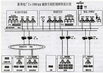 It can be seen that the centralized monitoring of auxiliary systems (workshops) is of great significance, which is mainly reflected in improving management efficiency, saving construction costs, and reducing maintenance difficulty. Therefore, from the very beginning, the power plant must have a unified plan. In the end, it will be possible to reduce both the investment cost and the automation level.
Introduction The auxiliary systems (workshops) are located far apart from each other in terms of physical locations, the traditional control methods are relatively independent, and the forms of network connections are diverse, thus inconveniencing monitoring and management. In recent years, due to the continuous development of control technology and the continuous renewal of management concepts, thermal power plants have put forward higher requirements for the monitoring system of auxiliary systems: not only to reduce investment, but also to improve the control level of auxiliary systems (workshops). Therefore, the control of the auxiliary system should improve the management and integration level of the auxiliary system (workshop) of the power plant by strengthening management and reducing the number of shifts.
I. Status of auxiliary system (workshop) control
In 2000, the coal-fired demonstration power plant and the newly promulgated "Technical Regulations for Design of Thermal Power Plants" put forward new requirements for the control methods of auxiliary systems (workshops), that is, "adjacent auxiliary production workshops or similar auxiliary process systems should be merged. The control system and control points, auxiliary workshop control points should not exceed three (coal, ash, and water), and the remaining workshops are designed according to unattended operation. The control technology of PLC+ PC is widely used in auxiliary systems (workshops) because of the enhanced safety and reliability of independent system operation. The status of the auxiliary control system can be summarized as follows:
(1) Most of the auxiliary control systems use more than 3 sets of PLC+ PCs, with more duty points.
(2) Some process equipment comes with a small PLC to control and form an independent control system.
(3) The auxiliary control system is often supplied by different manufacturers, resulting in different design styles and the types of PLCs, CPUs, and card types of each control system are not uniform.
(4) The main auxiliary systems such as coal transportation system, fuel pump room, ash removal system, chemical water treatment system, and circulating water system need to provide a special control room and a certain number of operating personnel to perform on-duty operation.
(5) Each control system is independent of each other, and there is almost no information exchange between system information and each main control room.
Therefore, the status quo of auxiliary systems (workshops) brings the following problems to operation and maintenance:
(1) The decentralized control room not only increases investment and operation and maintenance costs (such as decoration, air conditioning, etc.), but also is not easy to manage.
(2) There are more staff on duty. General crew masters are equipped with 5 crews per crew, and staff on duty for external equipment can be equipped with around 15 staff.
(3) There is very little information exchange between each auxiliary system (workshop) and the main control room. The control requirements of the main control room for the auxiliary system (workshop) are often contacted by telephone. This method is extremely inconvenient and lacks timeliness.
(4) Each auxiliary control system uses different hardware and software, which poses certain difficulties for spare parts management, personnel training and maintenance.
Second, the auxiliary system (workshop) centralized monitoring program research
2.1 Design of centralized monitoring points for auxiliary systems (workshops) Article 4.1.8 of the DL/T5227-2005 Technical Regulations for Thermal Power Plant Auxiliary Systems (Workshops) Thermal Engineering Designation clearly states that “auxiliary (system) workshops should adopt PLC control, Small DCS or dedicated controllers can also be used for technical and economic verification." Therefore, starting from a technical point of view, centralized monitoring of auxiliary systems (workshops) can be implemented using both PLC and DCS. According to “Technical Regulations for Thermal Industrial Automation Design of Thermal Power Plant Auxiliary System (Workshop)â€, the auxiliary system (workshop) may consider setting up two on-duty monitoring points and four backup monitoring points.
A monitoring duty point is set in the unit control room, equipped with 3 sets of auxiliary workshop control system operator stations (2 report printers). The monitoring target is the waterworks system. In the future, as required, ash and other systems can also be operated; another monitoring duty. Located in desulfurization control room, equipped with 3 sets of auxiliary workshop control system operator stations (2 report printers), desulfurization engineers configure 1 set of auxiliary workshop control system engineer stations, 1 set of SIS interface machines, monitoring objects for coal conveying, Ash slag system. The four backup monitoring points are considered by unattended personnel. They are chemical water treatment backup monitoring points, coal transportation backup monitoring points, ash residue monitoring points, and condensate polishing treatment monitoring points. The standby monitoring point is used for debugging, maintenance and operation during trial operation. It should have independent monitoring capabilities and configuration debugging capabilities for this system. Two sets of operator stations are set for the ash reserve monitoring point and the condensate polishing treatment monitoring point. Each of the other backup monitoring points has one set of operator stations. The operator station should have the function of the engineer station. No matter whether it is the on-duty monitoring point operator station of the auxiliary workshop centralized control system or the standby monitoring point operator station can monitor the entire auxiliary workshop, the actual monitoring range is determined according to the permission setting.
2.2 Auxiliary System (Workshop) Centralized Monitoring Network Design
2.2.1 Technical Requirements for Centralized Monitoring Network Since the auxiliary systems (workshops) have scattered physical locations and long distances, their network switches must be redundantly configured to ensure that the backup loops are automatically connected in the event of any network connection failure. There will be no data loss and data changes in the middle. Each auxiliary workshop sub-control system can work independently to ensure the safety of each system workshop and equipment. The auxiliary system (workshop) centralized monitoring system has a diagnostic function and a high degree of reliability. When two centralized monitoring points and the network fail, the lower backup monitoring points can monitor and ensure that the auxiliary systems work safely and normally.
2.2.2 Central monitoring The monitoring of the network design assistance system (workshop) centralized monitoring network consists of the following three layers:
First floor: 4 backup monitoring point control networks. This layer is used for system startup, initial commissioning, initial operation and failure. Two branch switch with optical uplink interfaces are configured at the backup monitoring point. Two PCI 100M Ethernet NICs are inserted into each host/server of the system. The controller is configured with redundant Ethernet interfaces and the access is different. Switch.
Second level: Auxiliary system (workshop) centralized monitoring network. The auxiliary system (workshop) centrally controls the on-duty monitoring point, configures two redundant optical fiber main switches, and the operator station and the engineering station, and the data server each inserts two PCI 100M Ethernet cards and respectively accesses different fiber main switches. The second layer of monitoring system is composed of optical fiber, optical fiber main switch and operator station.
Level 3: Auxiliary system (workshop) Centralized monitoring network The information system is connected to the SIS through a firewall and a gateway computer. The gateway computer has a network isolation function and can ensure that the auxiliary system (workshop) sends real-time data to the SIS without affecting the centralized control of the auxiliary workshop. The control function of the net itself.
2.2.3 Centralized Monitoring of Network Topologies Common network topologies include bus topologies, star topologies, ring topologies, and hybrids. The auxiliary system (workshop) centralized monitoring network uses a hybrid network, first forming a sub-network (for example, water network, coal network, and gray network), and then connecting the sub-network switch to the main switch. The use of hybrid topology in engineering applications can overcome the shortcomings of common star topologies and ring topologies, greatly improving the reliability, scalability, stability, and security of the network while improving the network's price/performance ratio.
2.3 Power supply and grounding design for centralized monitoring of auxiliary systems (workshops)
2.3.1 Control system power supply design In order to ensure that the control system can operate safely and reliably, the water supply, coal transport, and ash removal system should have separate power supply devices. Since the centralized control room is far from the various process systems, an independent power supply device is also configured. Factory power supply control of the auxiliary system (workshop) is controlled in the host common DCS. When configuring the control system power supply, it must be considered that after the system is powered off, the control system can still maintain normal power supply for one hour. Each power supply unit is required to receive two different sections of 400 VAC power supply, and then supply power to the equipment through a power supply switching device (preferably a UPS power supply) in the power supply cabinet. Each power supply device not only has to meet the power supply requirements of its respective control system, but also has to satisfy the power supply of the relevant control equipment (eg solenoid valve box, chemical analysis instrument, etc.) and leave a 40% margin. The power supply scope of the control system includes: control system equipment (controllers, I/O cards, network equipment, operation stations, etc.), solenoid valve boxes, transmitters, and analytical instruments.
2.3.2 Auxiliary system (workshop) centralized control grounding design Because the centralized monitoring of the entire auxiliary system (workshop) is widely distributed, centralized grounding should not be used. The grounding point can be considered to adopt the equipotential grounding method, and the single-point grounding is directly connected to each electrical grounding network. In this way, even if there is a lightning strike or an electrical short circuit occurs, the potential difference between the grounding points will not occur between the internal devices of the control system, which will damage the equipment and endanger personal safety. The remote cabinets and subsystems are connected by optical fibers to achieve complete electrical isolation. Even if the ground potential is not equal due to different grounding resistance, it will not affect the control system. The grounding copper bars shall be provided in the control cabinet. Each module rack and power supply rack shall be equipped with a grounding terminal. The grounding points shall be collected in the grounding copper bar in the cabinet, and then be connected to the electrical grounding grid. The grounding resistance should be less than 5 ohms. The shielding of the shielded cable should be grounded in the shielded ground of the control cabinet to ensure that one end is grounded. Water nets, coal nets, grey nets and remote stations should be connected by optical cables so that the electrical isolation between the various subsystems can be fully implemented to prevent the potential difference of the grounding point from affecting the normal operation of the system equipment.
III. Application and development prospects of centralized monitoring of auxiliary systems (workshops) Guodian Taizhou Power Plant Phase I construction of 2×1000MW ultra-supercritical units. Ultra-supercritical units have higher requirements in terms of safety, stability, economical performance, etc., and new requirements are also put forward for the operation and management of auxiliary systems (workshops). Through the above analysis, the Taizhou Power Plant auxiliary control system (workshop) centralized control system with cover is divided as follows:
(1) Integrated pump room and hydrogen station equipped with a set of control subsystems;
(2) A set of control subsystems for industrial wastewater treatment, chlorinating circulating water, scale inhibitor for slag water, domestic sewage treatment and coal slime wastewater treatment;
(3) A set of control subsystems for the purified water treatment, chemical desalination and regeneration system;
(4) A set of control subsystems for the condensate polishing and regeneration equipment and the soda water sampling and dosing system for each unit are totaled in two sets.
(5) A coal control system is equipped with a set of control subsystems;
(6) Each unit slag removal system is equipped with a set of control subsystems;
(7) A set of control subsystems are allocated to each unit's ash removal system;
(8) Each unit of the electrostatic precipitator system is equipped with a set of control subsystems;
(9) A set of control subsystems are configured in the grey reservoir area.
The network structure of centralized monitoring of the auxiliary system (workshop) of State Power Taizhou Power Plant is shown in the following figure. The system adopts DCS to realize the integration monitoring of auxiliary workshops. Through this program, the auxiliary system (workshop) of Taizhou Power Plant reduced the on-duty monitoring point (control room) and the configuration of the operating personnel and reduced the investment. Realize the logical concentration from the system, improve the automation level of the whole plant, and point out the direction for the development of new power plants in the future.
Rotary Vane Pump,Harbor Freight Vacuum Pump,Liquid Ring Vacuum Pump,Water Vacuum Pump
Dongguan Beqile Mechanical&Electrical Equipment CO.,LTD , https://www.betemvacuum.com